

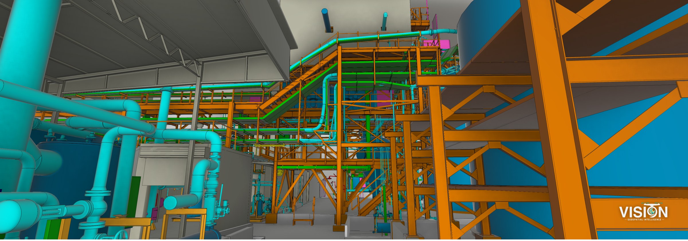
Level of detail in industrial 3D models
Download the guide (PDF)Detail and fit to the scan
We model plants and mechanical facilities from the point cloud. More detail means more modeling time and a larger file, so we choose the level by what the model will be used for.
Before modeling starts we agree two things with you: the level of detail for each kind of element, and the largest difference allowed between the model and the point cloud. One area or one kind of element can take a higher level than the rest.
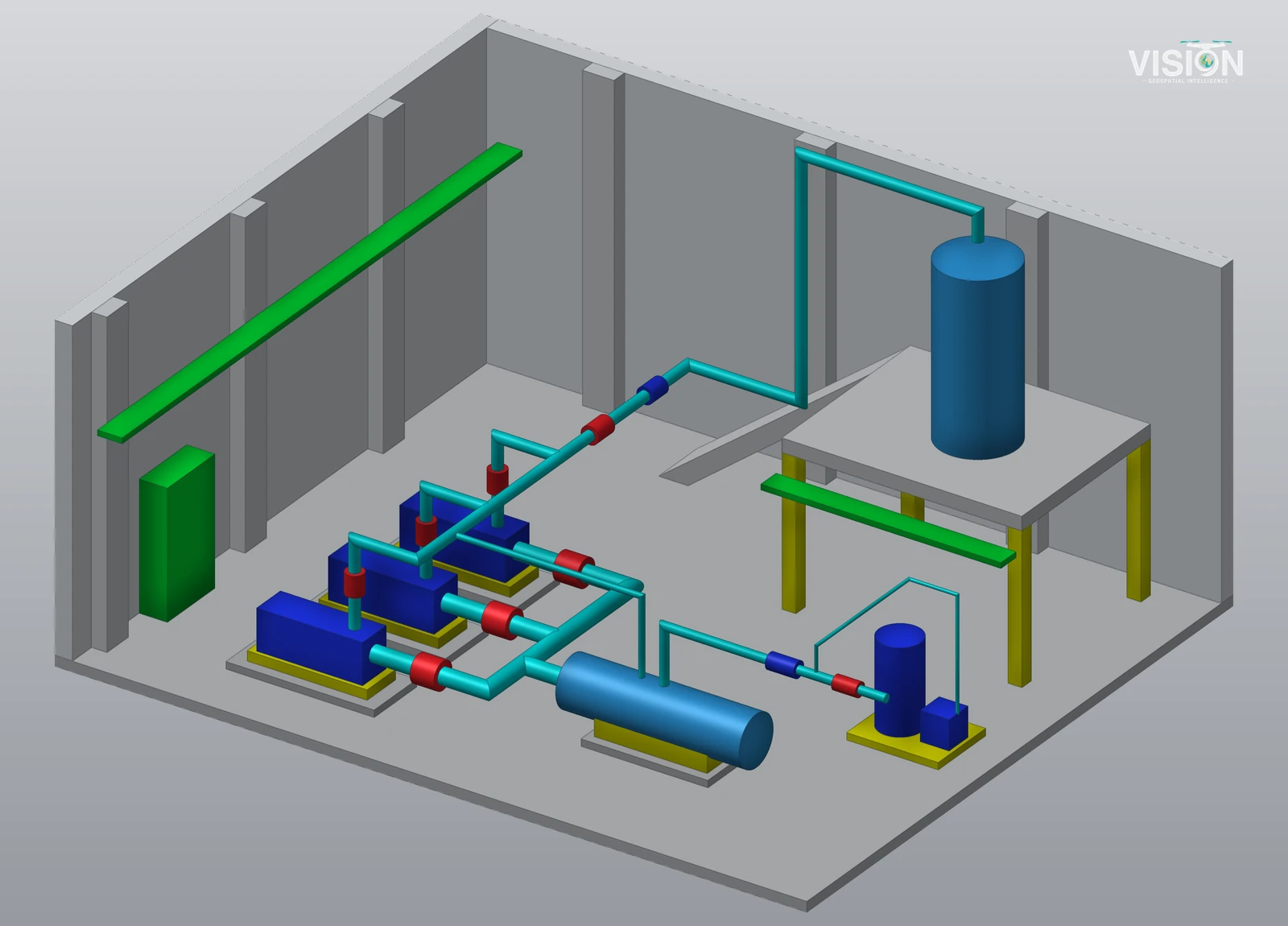
Level 1 Overall shapes
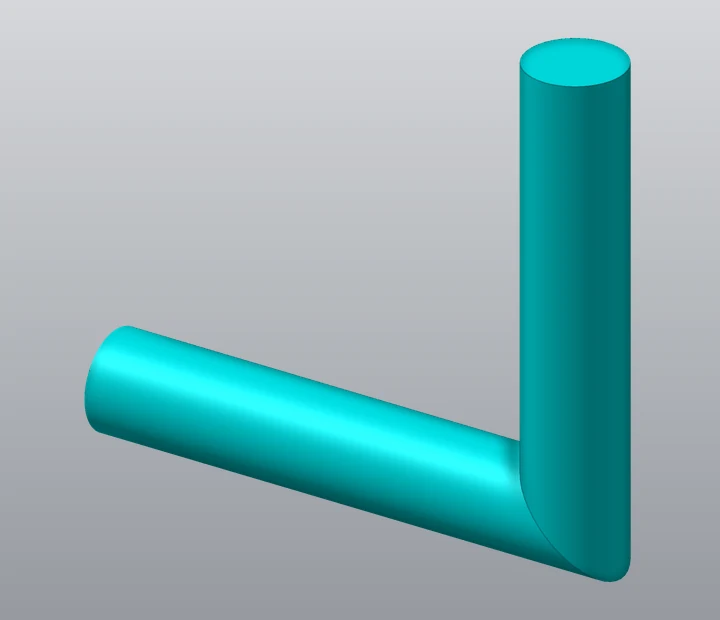
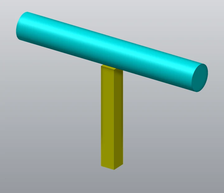
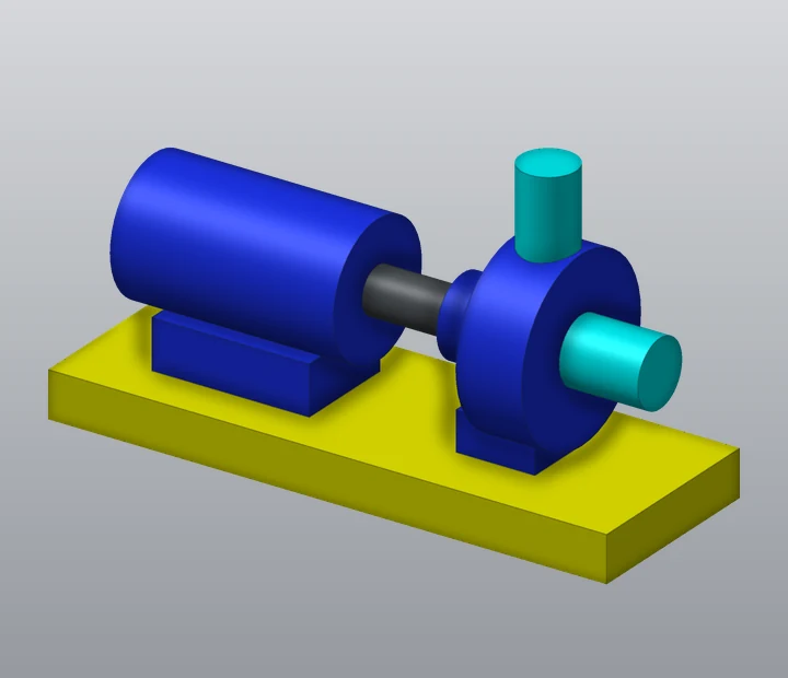
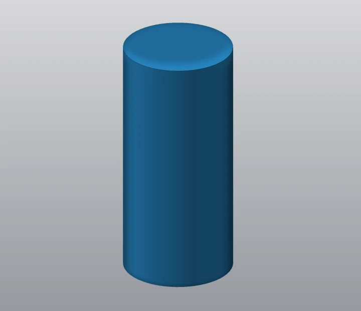
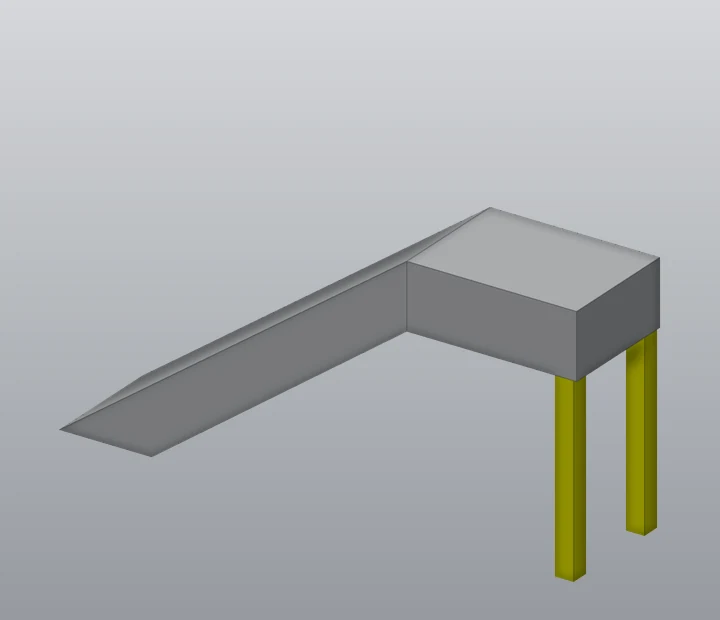
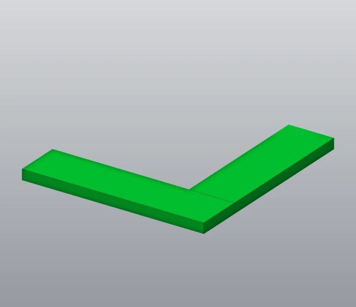
Each element is shown by its overall shape and position: equipment as simple volumes, pipes with sharp corners, steel as solid sections. It suits layout studies of large installations and clash checks.
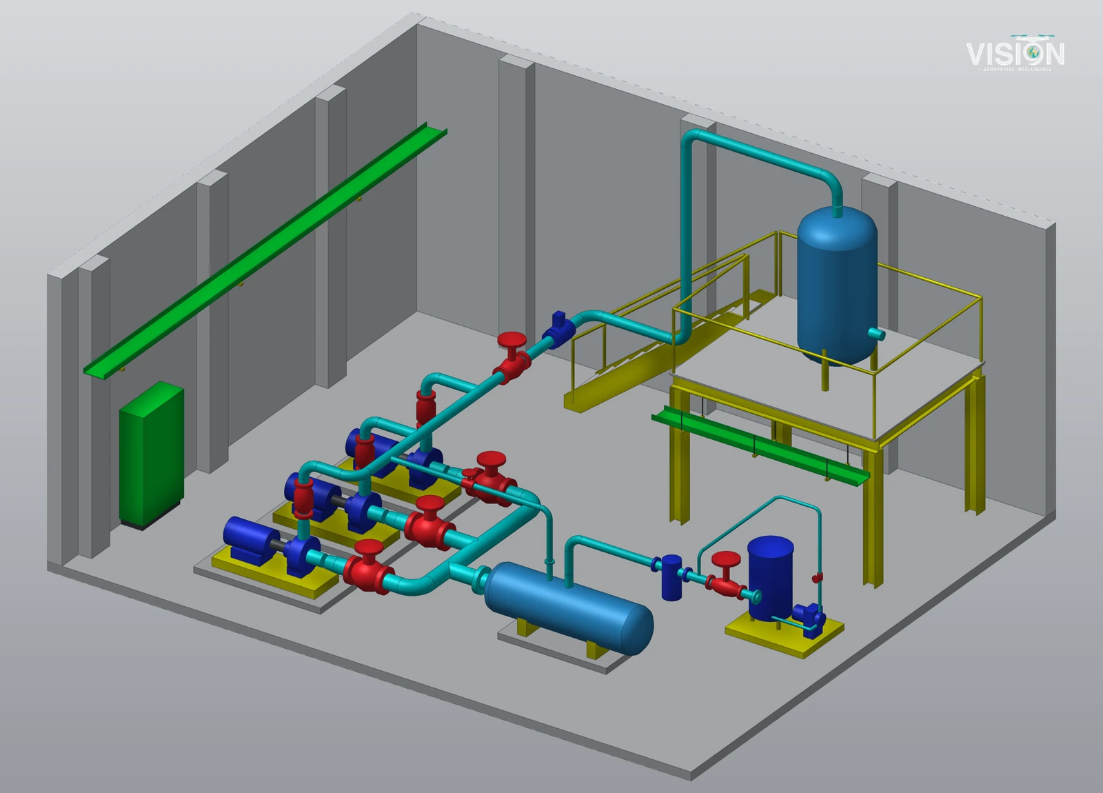
Level 2 The usual choice
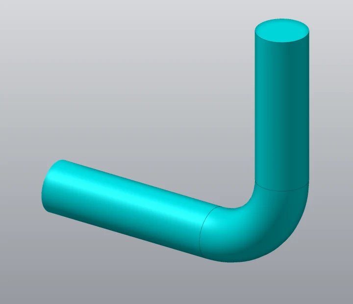
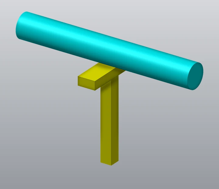
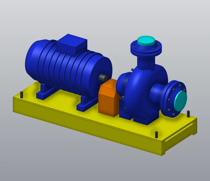
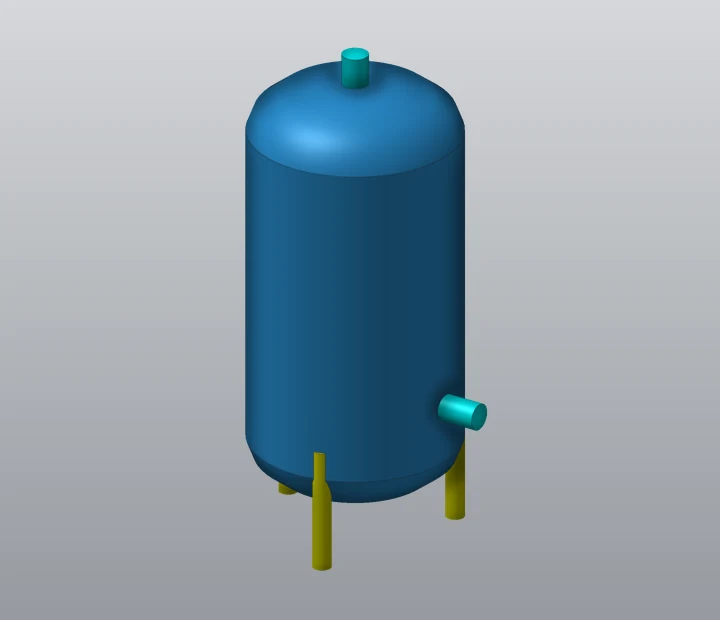
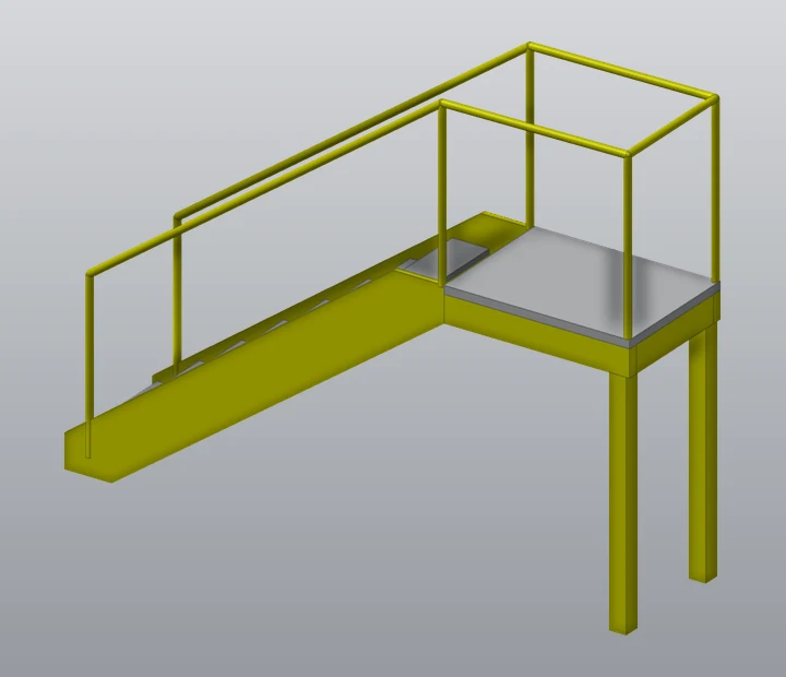
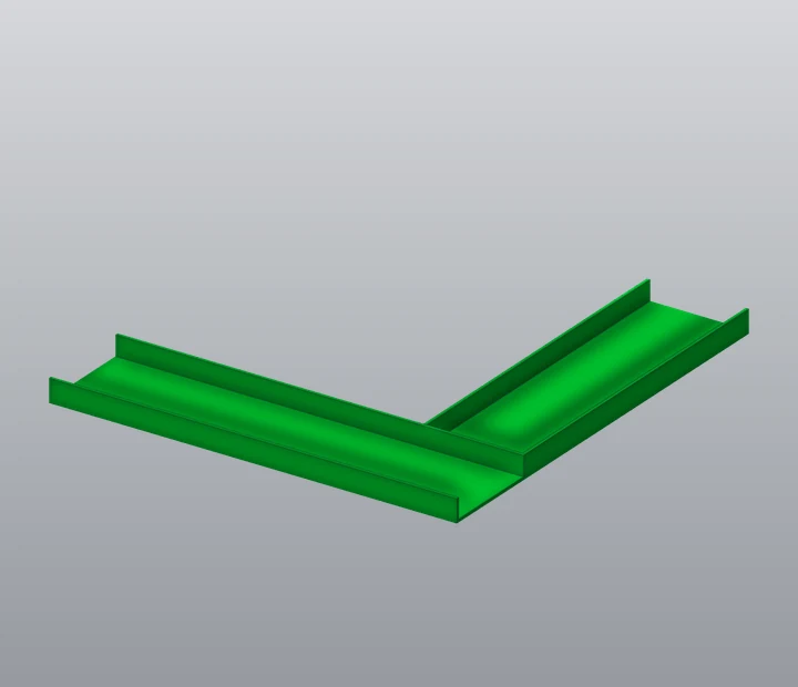
Equipment takes its real form, pipes get their bends, flanges and valves, steel is modeled with its true sections, and stairs and handrails are included. It balances detail against modeling time and suits most engineering uses.
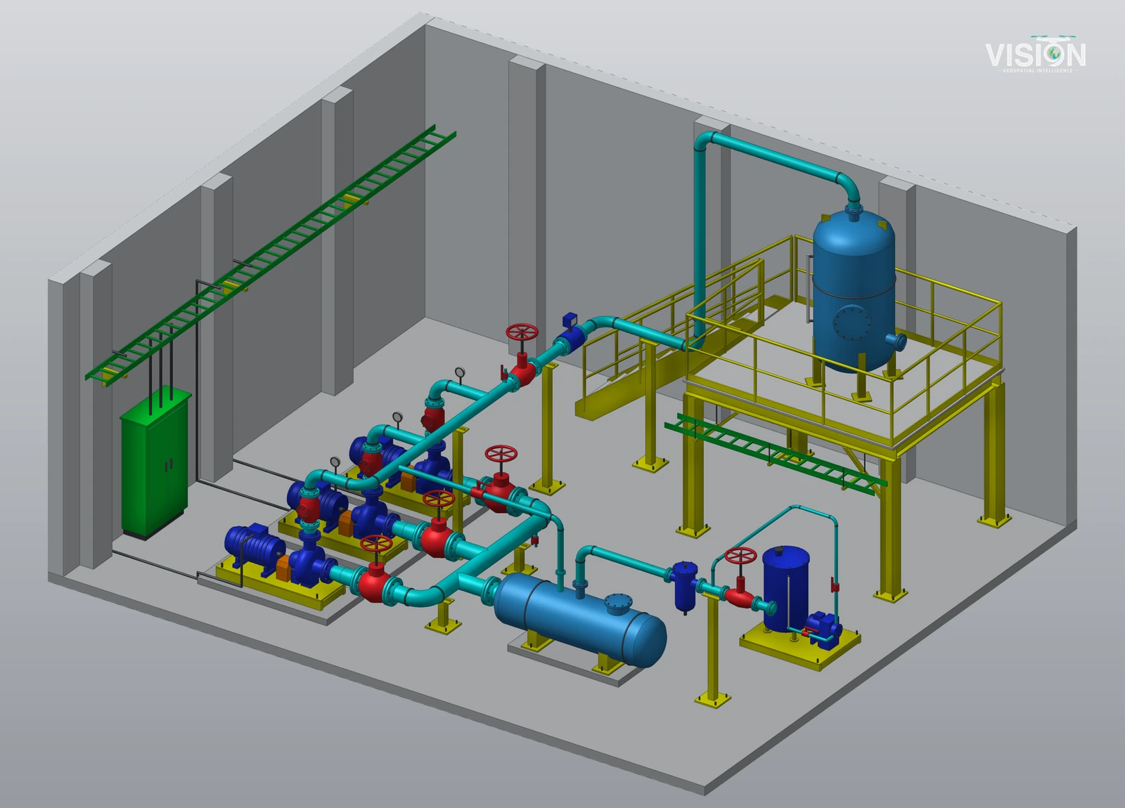
Level 3 Connections and fittings
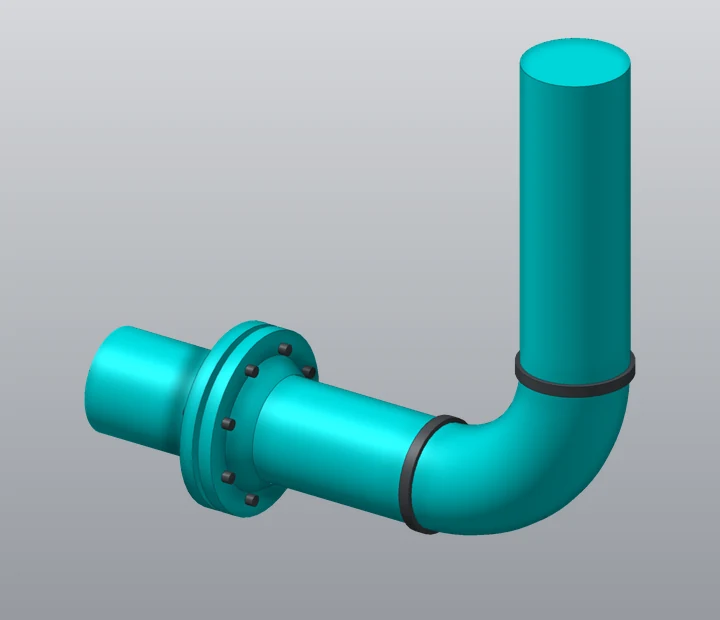
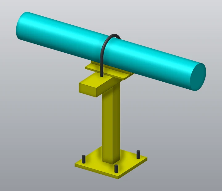
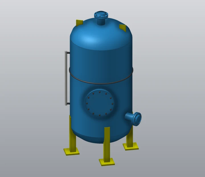
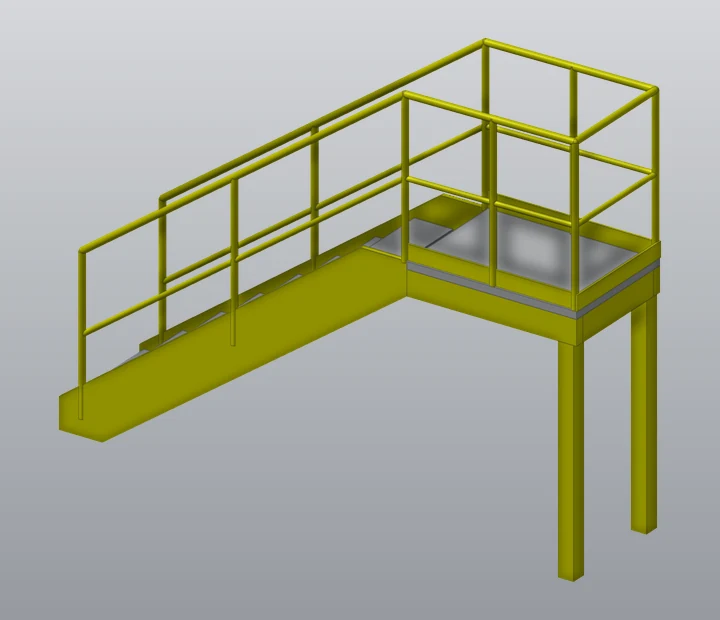
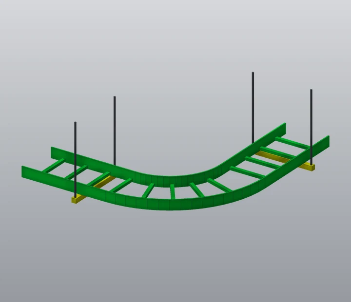
Adds bolted connections, nozzles, supports, base plates, cable ladders and small fittings. It is used for visualization and for design work where space is tight. It takes noticeably more modeling time, so it is often applied to selected areas only.
The same components at each level
Pipe bend
Valve
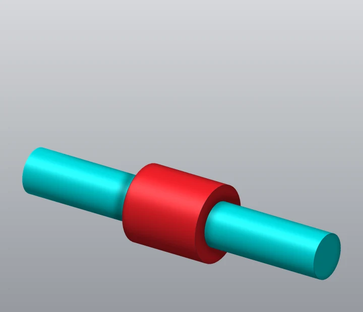
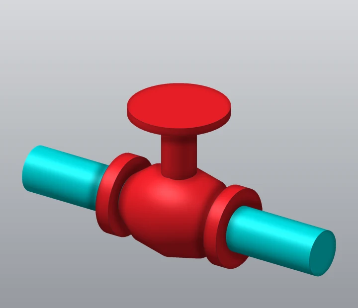
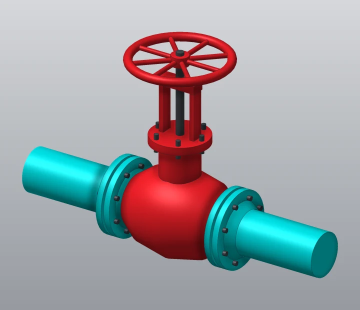
Flanged joint
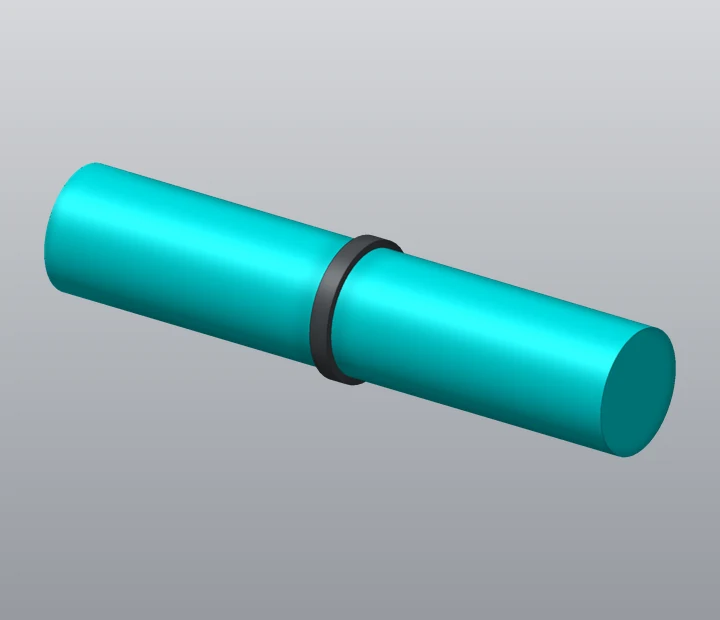
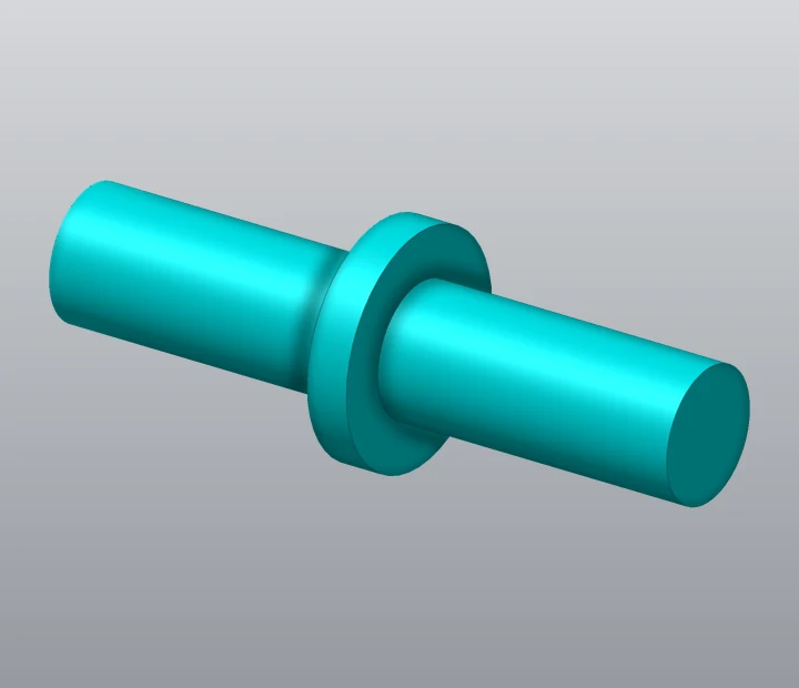
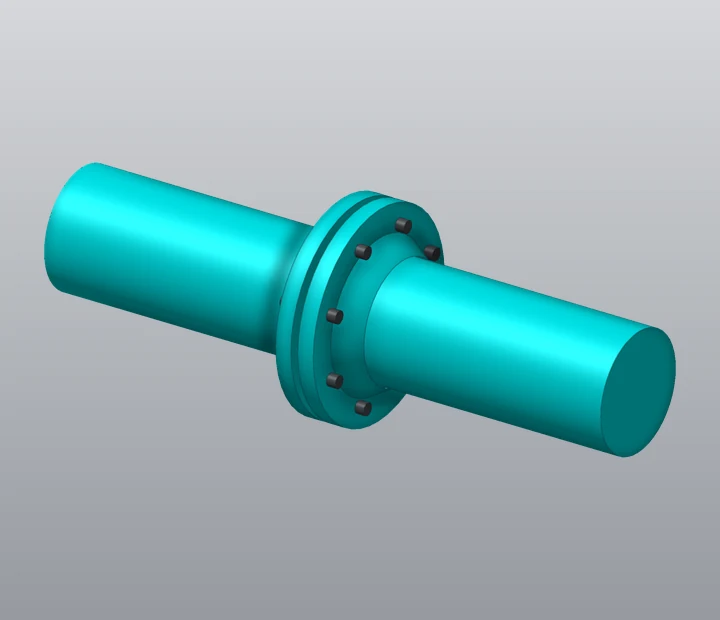
Steel column and beam
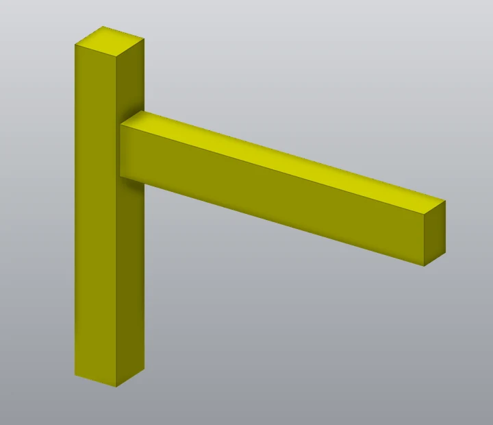
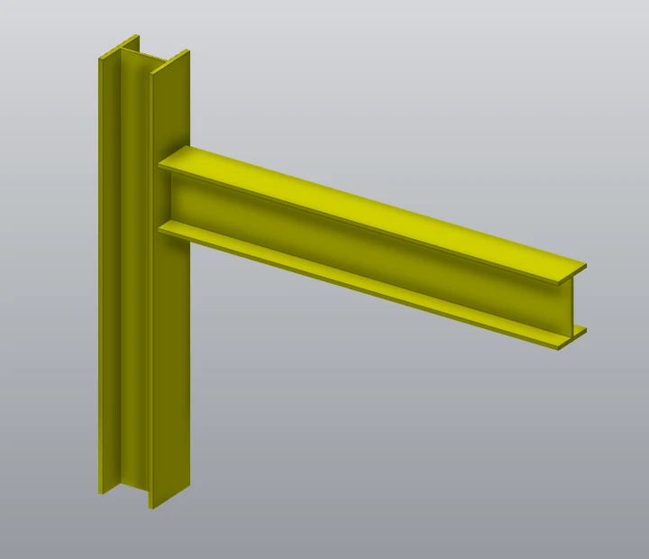
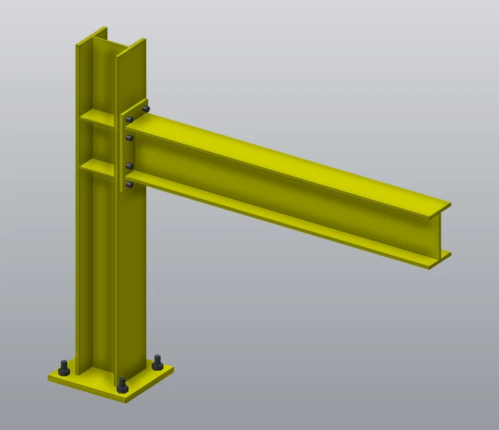
Pipe support
Pump set
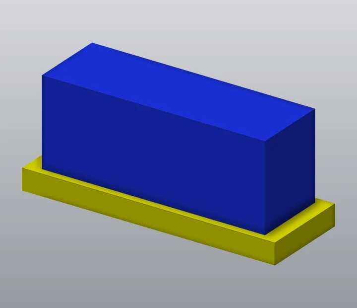
Vessel
Stair and handrail
Cable tray
Modeling tolerance
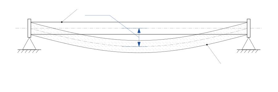
Pipes sag and beams deflect, so a straight element in the model never lies exactly on the scan. The tolerance is the largest distance we accept between the two. A tighter tolerance means more segments and more modeling time. We set its value with you, for pipes and for structural members, and record it in the scope of work.
Choosing a level
Tell us what the model is for and we will recommend a level for each kind of element. Detail beyond what the use needs adds modeling time without adding value.
Request a quotation